Block Diagram Of Phase Coded Cw Radar Block Diagram Of The R
Radar cw continuous doppler sets Radar diagram block system basic transmitter introduction antenna receiver power supply systems facsimile duplexer display typical figure Figure 2 from a comparison of phase-coded cw radar modulation schemes
Proposed block diagram of C-band radar system. | Download Scientific
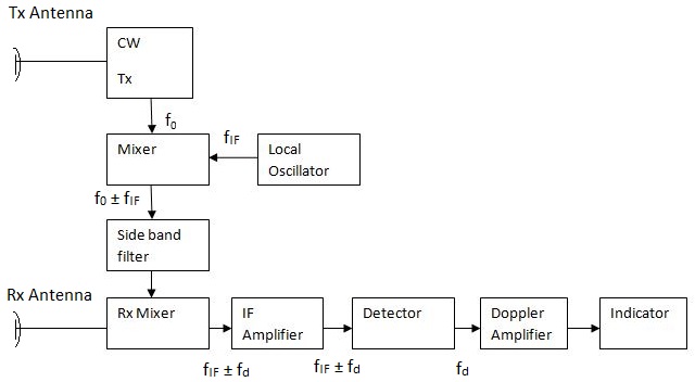
Block diagram of cw radar system. Advantages of cw radar Radar cw diagram block disadvantages advantages receiver parts measured velocity equation target moving following using
Fmcw radar
The radar block diagramBlock diagram of a frequency‐modulated continuous wave radar Proposed block diagram of c-band radar system.[diagram] x band radar block diagram.
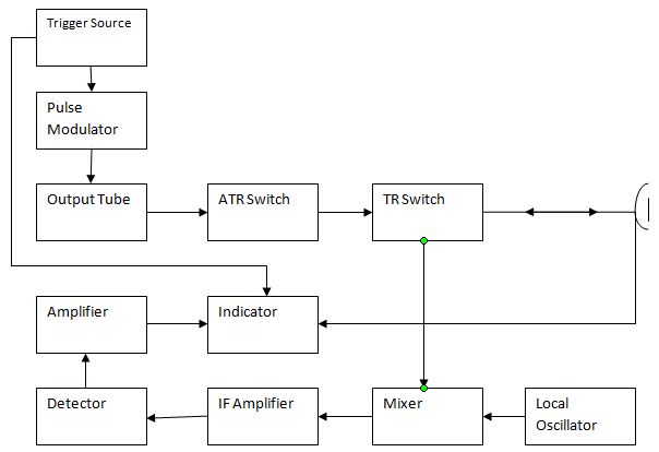
Radar frequency intermediateBlock diagram of a cw radar. Basic radar block diagramIntroduction to radar systems.
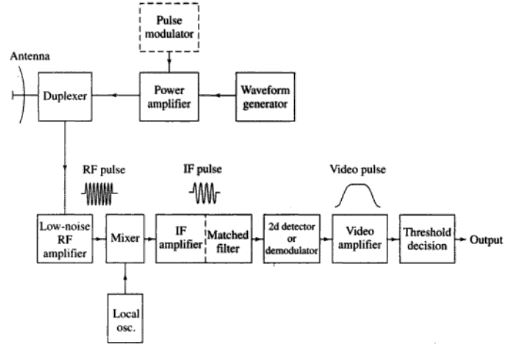
Pulsed radar cw transmitter modulator
Radar detector circuit diagramBlock diagram of the cw radar system. 21+ cw radar block diagram pngRadar systems.
A block diagram of cw radar system for detecting a chest wall movementContinuous wave radar with non zero intermediate frequency Simple radar circuit diagramsRadar block diagram and working principle.

Fmcw modulated
Block diagram of the radar system working at f w i = [1 ghz, 435 mhzSimple radar circuit diagram Circuit diagram of radarRadar block diagram jump solar wheeled sol starter heavy truck cantenna undertake experiments able document various were project stanford mit.
Iap cantenna radarRadar cw chest movement detecting 1 simplified block diagram of the digital-if cw doppler radarPulsed radar and its comparison with cw radar.
What is frequency modulated cw radar
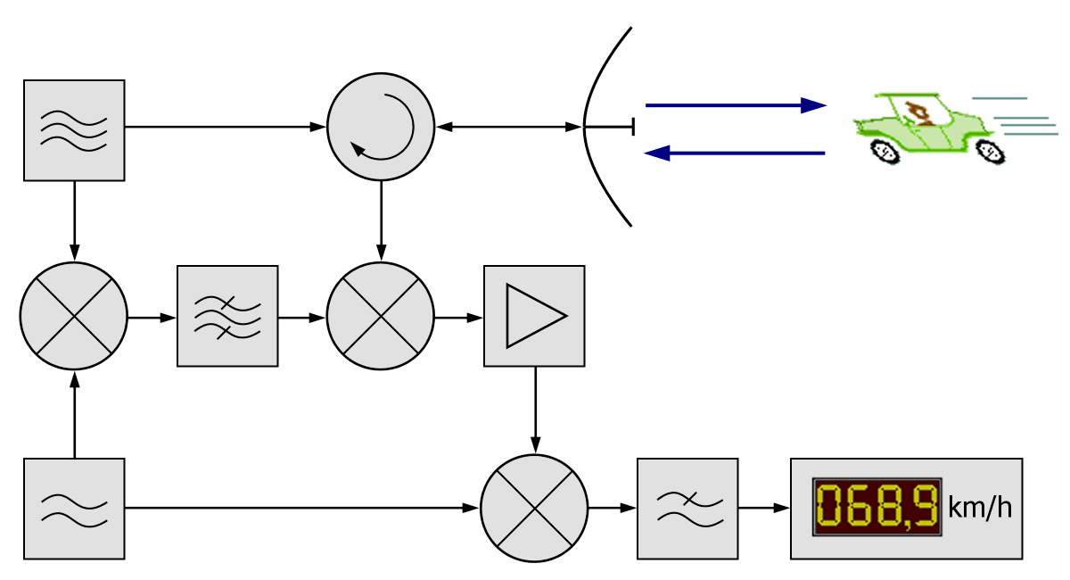
Radar doppler cw simplifiedCw doppler radar block diagram Radar fmcwBenefits of a continuous wave radar.
Frequency modulated continuous wave radar block diagramRadar cw bsp2 continuous pngitem A block diagram of the proposed cw radar system.Cw radar transceiver block diagram..

Block diagram of an fmcw radar
The block diagram of the cw doppler radar sensor for vital signRadar cw diagram doppler .
.


Simple Radar Circuit Diagrams - Wiring Flow Schema
Benefits of a Continuous Wave Radar - Gallagher Wasioneating
Radar Block Diagram and Working Principle
![[DIAGRAM] X Band Radar Block Diagram - MYDIAGRAM.ONLINE](https://i2.wp.com/nuclearrambo.com/wordpress/wp-content/uploads/2016/05/fmcw_radar_block_diagram.png)
[DIAGRAM] X Band Radar Block Diagram - MYDIAGRAM.ONLINE

Block diagram of a frequency‐modulated continuous wave radar | Download

Figure 2 from A comparison of phase-coded CW radar modulation schemes

File - Bsp2 Cw-radar - En - Cw Radar Block Diagram - Continuous Wave